|
Part 2
REMOTE
VOLTAGE-SENSING (for
the voltage regulator)
About the car
used for the “working model”
with
this REMOTE VOLTAGE-SENSING demonstration…
This
car was the best choice we had at our facility, when we
were shooting the photos.
It has an easy to access, stock, 12SI Delco
alternator, and genuine Delco voltage regulator in the
alternator.
The car also has five electric fans, lights, two
batteries, and other accessories to switch ON and use
power from the alternator.
(Which we needed, because significant voltage drop
would only occur with a large amount of current flow.)

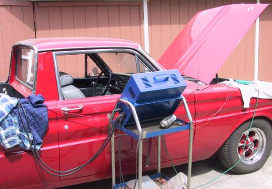
We
used a SUN model VAT 40 (VAT for Volt, Amp, Tester), to
monitor system function and performance, and to measure
voltage drop in the long alternator output wire.
It was a handy arrangement that allowed for photos
of the VAT 40 meters, shot through the passenger side
window, while operating the car.
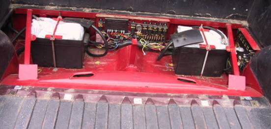
The
batteries and electrical control center in the car is
beneath the cargo bed, which is just behind the cab in the
custom Ranchero.
With removal of four screws, we lifted off the
cargo bed floor for access to show you this test.
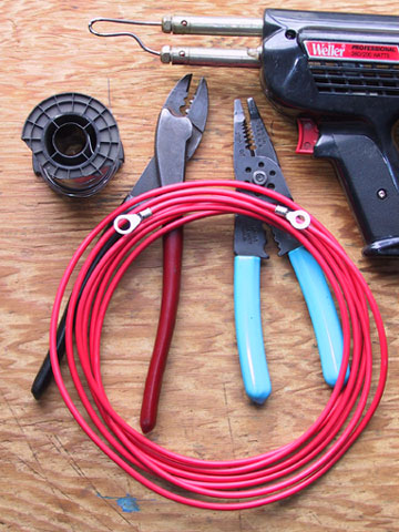
For
the test demonstration, we prepared a 12 ft. length of
10gauge wire, which would connect between the alternator
output terminal and the
“main-power-distribution-junction.”
Chevy with V-8 engine in ’69,’70, and ’71
will have a 10gauge wire approximately this long, between
the alternator and the “main junction.”
Our test wire would give us a good representation
of what to expect with a typical factory built Chevy
system.
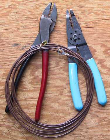
And
we also prepared a 12ft. long voltage-sensing wire, which
would connect from the voltage regulator in the alternator
to the “main power distribution junction.”
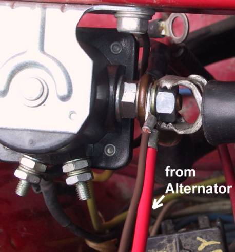
The
main “junction” at the Ranchero system, is the battery
POSITIVE cable stud, at the remote starter solenoid, which
is in the battery compartment.
We disconnected and set aside the existing 8 gauge
Tuff-Wire alternator wire at the junction. And we connected the prepared 12 feet long 10 gauge
alternator output wire and the voltage-sensing wire to the
battery POSITIVE stud at the remote solenoid.
The
battery positive stud at the solenoid connects to the
battery by 1/0 gauge, fine strand copper conductor cable,
and so during our tests, voltage measured at the battery
will be the same as voltage at this stud, which serves as
the main “junction” in this electrical system.
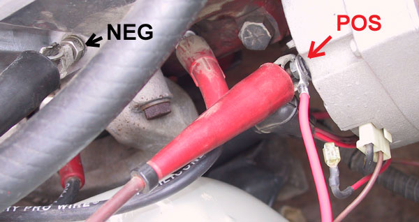
Moving
to the alternator area, under the hood, we connected the
12 feet long 10 gauge red wire to the output stud terminal
at the back of the 12SI alternator.
And we connected the voltage-sensing wire to the
regulator terminal at the two-wire plug-in connector.
We
also connected the EXTERNAL VOLT METER leads of the Sun
Vat 40. The
NEG voltmeter lead is connected to a clean, valve cover
stud at the engine. And
the POSITIVE VOLT METER lead is connected directly to the
alternator output stud.
This
would allow the SUN VAT 40 to read voltage at the
alternator, during testing.

For
many years, the VAT 40 was the most popular of equipment
in professional automotive shops concerned with testing
alternator systems, starters, batteries, and voltage drop
problems.
In
alternator test mode, the BLUE, 0-100 AMP scale at the
upper meter is the one we are reading.
And the GREEN 0-18volt scale will apply to testing,
except when actually measuring voltage drop across a
cable. For
voltage drop testing the 0-3volt scale is more sensitive
and accurate, this setting is available when the VOLT
SELECTOR is switched to “EXT. 3V.”
Notice
the “VOLT SELECTOR” switch, at the lower left corner
of the photo. A
close up of the switch is shown in a photo below.
We will explain the switch and call out the setting
of the switch throughout this photo series.

When
the VOLT SELECTOR switch is set to “INT. 18V.” the
voltmeter in the VAT 40 reads from the large clamps
connected directly to the battery.
(Shown in next photo)
Set to “EXT. 18V. the VOLTMETER on the SUN VAT 40
reads from the small volt meter leads, which were shown
connected to the alternator in a previous photo.
And when set to “EXT. 3V.” the VAT 40 reads
voltage from the external voltmeter leads and displays the
reading on the 0 to 3 VOLT (black scale) at the voltmeter.
This 3 volt scale is very useful when measuring
voltage drop through a cable or wire.
Simply connect a volt meter lead at each end of the
wire, power up the circuit, and the voltage drop in the
wire (or cable) will be displayed on the 3 volt scale to
the nearest tenth of a volt.
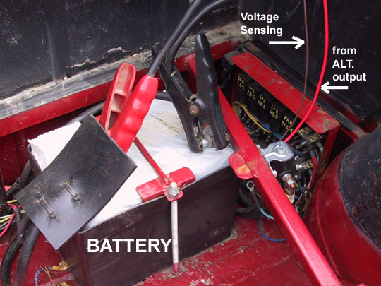
The
large cables of the VAT 40 (booster cable/jump start like
clamps) are connected directly to the battery terminals.
These cables will allow the VAT 40 to read voltage
at the battery, when the selector is switched to INT. 18V.
These large cables also power-up the inductive AMP
meter built into the VAT 40.
(And these large cables may also be used to “load
test” a battery, with the adjustable “carbon pile”
LOAD TESTER BUILT INTO THE vat 40.)

The
AMP gauge in the VAT 40 reads current flow through a wire
simply by clamping the green probe around the wire (or
cable). Here
we have placed the probe around the 12 feet long red 10
gauge wire, where the VAT 40 can read alternator output.
(A distant view of this AMP PROBE is visible in the
second photo at this web page, which is the photo showing
the overall set up for this test.
The green AMP probe is on the front fender, it’s
on the white sweatshirt.)

To
see photos of the VAT 40 meter displays during actual
testing,
|