|
Part 3, the
last section of the
REMOTE VOLTAGE-SENSING
TESTS
(actual test results in photos)
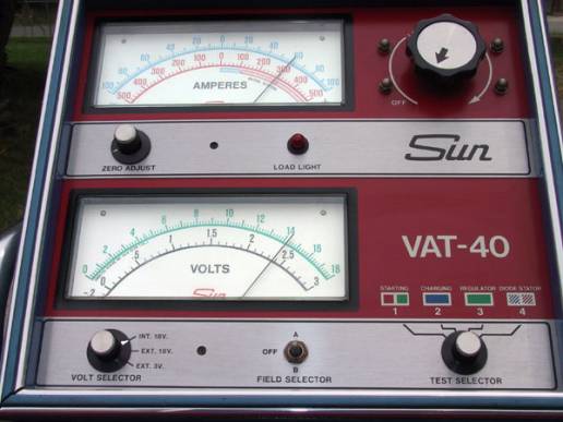
In
this first test, we have switched the VOLTMETER to INT.
18V., and we are reading voltage from the battery (and
main junction).
With the remote voltage-sensing wire connected, the
voltage regulator is adjusting voltage at the junction and
battery to exactly 14.2 volts.
We have switched on the lights, cooling fans, and
heater fan to use current from the main junction in this
electrical system (The junction is the positive stud on
the remote solenoid, next to the battery.
The
upper meter on the VAT 40 is indicating about a 60 amp
alternator output through the 12 feet of red 10 gauge
wire.
As the battery was nearly at a fully charged
condition, most of this alternator power output is being
used to support all the systems we have switched ON.
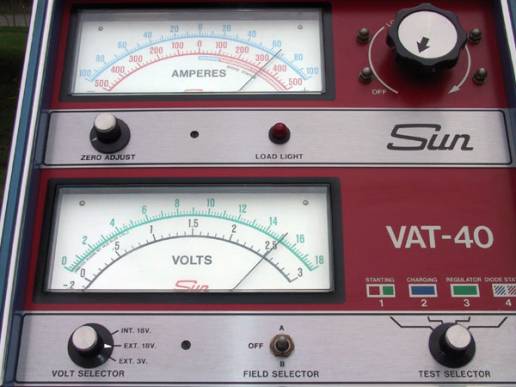
In
the photo above, we have switched the VOLT SELECTOR to
EXT. 18V., and now we are reading voltage at the back of
the alternator.
Voltage at the back of the alternator is almost
exactly 1 volt higher than it was at the battery in the
previous photo, as the remote voltage-sensing is
compensating for the voltage drop in the long alternator
output wire.
Alternator
output is slightly higher in this photo than the in the
previous, as we left the lights ON while taking a break to
answer a tech support phone call.
Now the alternator is supporting the cooling fans,
headlights, heater fan, and plus it is recharging the
battery!
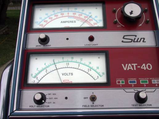
In
the above photo, we have switched the VOLT SELECTOR to
EXT. 3V. and connected the external voltmeter lead wires
in parallel with the 12 feet long 10 gauge alternator
output wire. Reading
the 3 VOLT, black scale at the lower meter, we are
measuring almost exactly a 1 volt drop in the long
alternator output wire.
(The next photo will show the external volt meter
lead connected at the “junction,” which is the battery
POSITIVE stud on the solenoid.)
The 1 volt drop is exactly the voltage difference
between the two previous photos, which compared the 15.2
volts at the back of the alternator to the 14.2 volts at
the junction.
This
directly measured voltage-drop test serves as a very good
cross-reference check to verify accuracy of
the voltage difference between the two previous
photos. (All
laboratory tests should have a “control test” or at
least a “cross-reference test” to verify accuracy.)
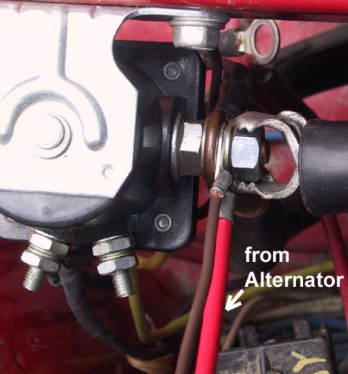
And
the above photo shows a close-up view of the external
voltmeter lead wire, connected to the junction/stud on the
solenoid.
(The alligator clip on the hex-nut at the stud is
the SUN model VAT 40 external voltmeter lead wire.)
This connection of the VAT 40 voltmeter was used
for the previous photo, where we measured a 1 volt drop on
the EXT. 3V. switch setting.
 The remote voltage-sensing feature is
not available with “ONE-WIRE” alternators. With the ONE-WIRE alternator, the internal voltage regulator
can only adjust voltage at the alternator.
To show how the ONE-WIRE alternator would behave in
this test, we let our existing THREE-WIRE alternator take
voltage-sensing sample from the output stud at the back of
the alternator. Then
voltage-sensing with our existing THREE-WIRE alternator
would behave the same as with a ONE-WIRE alternator.
 ONE-WIRE
alternator simulator test underway! ONE-WIRE
alternator simulator test underway!

We
made a short length wire, which would connect the
voltage-sensing terminal at the two-wire connector to the
output stud at the back of the alternator.
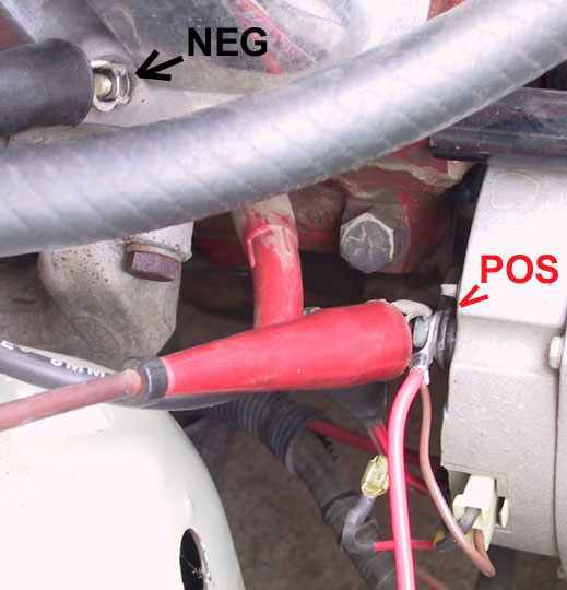
And
at the alternator wiring we removed the long length of
remote voltage-sensing wire, and installed our new jumper
wire. The
voltage regulator will now read voltage at the alternator
and make adjustments to output as required to maintain
about 14.2 volts at the alternator.
(Same as with the ONE-WIRE system.)
Also
notice in the above photo that we have once again
connected the EXTERNAL VOLT lead wires to the alternator,
so we can compare voltage at the alternator to voltage at
the battery.
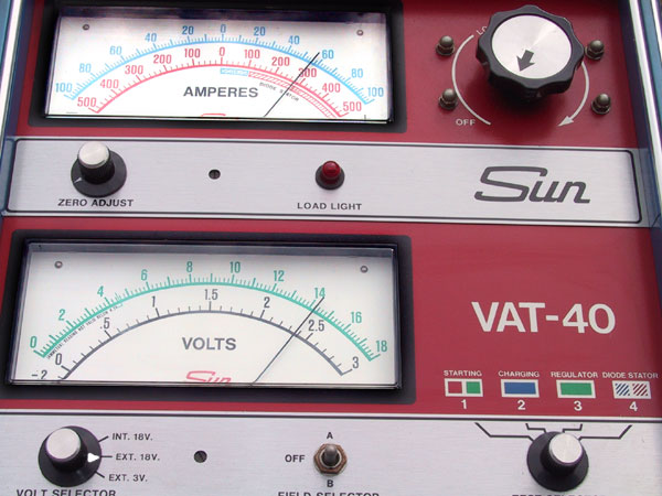
Notice
in the above photo we have switched the VOLTmeter to EXT.
18V., and we are now reading 14.2 volts at the alternator.
Also notice that the alternator is producing about
a 55AMP output, as once again we have switched ON the
cooling fans, lights, and heater fan, while running the
engine.
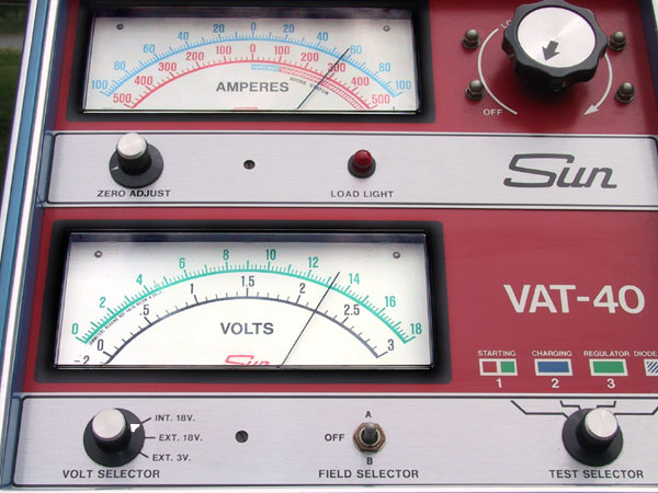
And
in the photo above, we have switched to INT. 18V., and now
we are reading voltage at the battery, which is next to
the main junction. The cooling fans, lights, and heater fan are all switched ON,
and we are still measuring about a 55AMP output from the
alternator.
But
now, voltage drop in the alternator output wire has
reduced voltage at the battery to the 13.2 volt level.
We
still have the same 1 volt drop in the 12 feet long, 10
gauge alternator output wire.
But with the voltage regulator making adjustments
at the alternator, we are left with low voltage at the
battery and main junction.
IN SUMARY
It
really pays to “charge ahead” with remote
voltage-sensing.
Our tests were representative of a factory wire
harness layout, with main-power distribution from a
junction in the wiring, and a long wire from the
alternator output to the junction.
NOTE
that the amount of resistance in a wire increases when the
wire is warm. (GM
engineering data shows about a 25% increase in resistance
when wire temperature is increased from 70 degrees to 160
degrees F.) Temperature
during this test was about 65 degrees F, which is cooler
than we would expect at the alternator output wire under
the hood of a Chevy. And this is especially important
considering that parts of the alternator output
wire and the battery charging wire are above the
radiator!) In
the case of wires being considerably warmer than with our
test, the amount of voltage drop would be greater with
increased resistance.
And then the REMOTE VOLTAGE-SENSING option becomes
even more important.
The
tests clearly show that REMOTE
VOLTAGE-SENSING is the key to good electrical system
performance when using this factory-type wiring layout.


See
more about remote voltage-sensing in our ONE-WIRE compared
to THREE-WIRE alternators page, in the ELECTRICAL TECH
section of this web site.
|