|
It all
STARTS with knowledge of how things work!

REMOTE
VOLTAGE-SENSING IS THE KEY TO GOOD ELECTRICAL SYSTEM
PERFORMANCE… It
lets the voltage regulator make adjustments where proper
voltage level will do the most good.
Remote
Voltage Sensing
is not a new idea;
in
fact many factory original systems have been using it
for years (even with external voltage regulators back in
the 1960’s).
All
voltage regulators take an electrical system reading,
and constantly monitor the voltage level of the system.
For most temperatures and conditions, the
textbook battery voltage level when topping off a fully
charged battery is about 14.2volts (with a 12 volt
system).
The voltage regulator will adjust alternator
output in effort to maintain that 14.2 volt level, under
normal operating conditions.
Therefore, most electrical system parts (lights,
ignition, and accessories) are designed for best
performance when operating at about 14volts.
Electrical system
performance drops off abruptly when voltage delivery to
the parts is only slightly low—and so we really like
to see those parts operating at 14volts!
With
involved wire harness construction used to deliver power
to various parts of the electrical system, some of the
wires will be long in length.
Most often, the dash area with switches and fuse
box is far from the alternator.
And under the hood, the battery may be at the
opposite side from alternator mounting, which will also
require a long wire. The
long length of wires will result with “voltage
drop.”
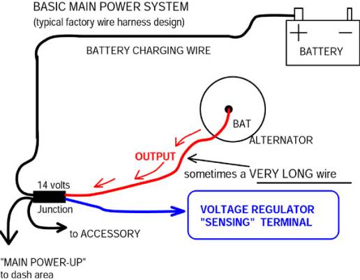
Considering
the spread-out location of electrical system parts on the
car, often the most efficient and practical layout is to
route alternator power output to a centrally located
“junction.” And
then from the junction, power will be distributed to
various parts of the electrical system.
Also the electrical current used to charge the
battery will be routed from the central main junction to
the battery. The
diagram above shows such a system; and it is a system that
was successfully used with many factory-built wire harness
layouts.
The
key to good performance
with
the layout described above is to let the voltage regulator
make adjustments to voltage level at the junction.
(And then the voltage at the battery and other
parts of the system will follow the voltage level
maintained at the junction.)
The voltage regulator can maintain 14.2 volts
at the junction, even though the junction may be many feet
of wire from the alternator.
But REMOTE VOLTAGE-SENSING must be
enabled to make it all happen.
The diagram above shows this basic layout; and it
was successfully used with many cars during the Muscle Car
period.
Certainly the Chevy design layout was this type
during the Muscle Car period.
(Although the particulars and location of
components did get moved around during that period of
years.)
When using this factory wire harness layout,
and up-grading to modern and more powerful alternators; it
is of critical importance to let the voltage regulator
read and adjust voltage at the junction.
And we call this function “REMOTE
VOLTAGE-SENSING.”
(“REMOTE” because the voltage regulator
takes care of voltage level at a place away from the
voltage regulator, alternator, and battery.)
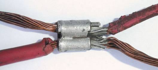
The
photo above shows an actual “main junction,” which we
removed from a Chevy factory original wire harness.
Note that the splice used for the factory
“junction” was crimped and soldered; these
factory splices are very reliable!
In our BASIC MAIN POWER diagram, we simply labeled
this part “junction.” When working with an original harness, which is in good
condition, capacity of the wiring and this junction is
adequate for alternators of moderate output.
(Output as much as the Delco 12SI 78amp unit works
fine, but REMOTE VOLTAGE SENSING must be properly wired.)
However,
as anyone can see, the junction is not friendly for
addition of accessories–The factory never intended to
add main power-up wires for electric radiator fans or
other high current draw accessories to this junction.
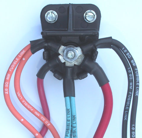
The
“junction” shown in the above photo is M.A.D.’s part
#CN-1.
This is the most sensible, compact, friendly to
work with junction in the industry.
When up-grading to high powered alternators, a new
heavy gauge cable can be routed from the alternator
directly to the this junction.
The factory dash area main power-up wire can be
transferred to this junction.
Many accessories can be added to the junction.
The battery charging wire of optional gauge size
can be routed from this junction to the battery.
And fusible link wire short circuit protection can
be installed at all outgoing circuits from the junction.
When customizing the “BASIC MAIN POWER SYSTEM”
shown in our diagram, this part#CN-1 is well suited for
the job!
The
OLD and the NEW,
both with REMOTE VOLTAGE-SENSING FEATURE
Back
in the old days,
when
our Chevy Muscle Cars were new, technology was more
primitive than today.
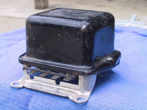
The above photo shows a typical external voltage
regulator used with most GM car alternator systems from
1963 thru 1972 models.
Of the four terminals at the voltage regulator, one
of the terminals served as the “voltage-sensing”
terminal, and it was wired to the “main junction.”
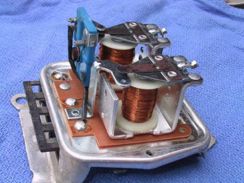
The
photo above shows construction inside of the old external
voltage regulator.
The original parts were mechanical, with two major
functions built in.
(1)
The “vibrating point type” voltage regulator is
at the foreground in the photo.
It’s a magnetic winding and moveable arm with
contact points assembly, and it was used to control
current to the alternator field winding.
(The points opened and closed many times per
second, thus it was often called the vibrating point type
regulator.)
Full current flowed to the alternator field when
the points were closed, making a strong magnetic field at
the alternator, which increases output.
It is interesting to note that when the points were
open in this system, current to the alternator field was
never entirely disconnected.
When the contact points were open, a small amount
of current still flowed to the alternator field through
resistors mounted at the underneath side of the regulator
assembly.
No doubt this action with the resistors smoothed
out the operation and reduced erosion of the voltage
limiter contact points.
And the system also needed to maintain at least a
small amount of alternator output to keep the “field
relay” turned ON.
(2)
The second magnetic winding with movable arm and
contact points was a “double throw” relay.
There are stationary contact points above and below
the contact at the movable arm.
Spring pull moved the arm to close one set of points,
which directed a small amount of current to the alternator
field, resulting with a small amount of alternator output.
When the alternator begins to make this small
amount of output, current from the alternator stator
powered up the magnetic winding, which pulled the movable
arm to close the other set of contact points.
As this other set of contacts closed, the regulator
was connected to main battery power source at the
“junction” in the wire harness.
When the system was first activated, a small amount of
current flowed from the ignition switch to the voltage
regulator through a 10 to 15 ohm resistance wire built
into the dash harness.
(And if the car had a warning light at the dash,
the warning light was wired in parallel with the
resistance wire.)
This was our ignition switched ON/OFF and warning
light circuit with the old externally regulated alternator
system.
And
through the “field relay” in the old external voltage
regulator, we had REMOTE VOLTAGE-SENSING from the main
“junction” in the wire harness.
 Not all systems had
the
REMOTE VOLTAGE-SENSING option.
Some
of us in workshops years ago, used to install this
“field relay” function, using an ordinary relay, to
create our own version of the REMOTE VOLTAGE-SENSING
function.
The MOPAR, two-wire voltage regulator system, both
the early mechanical and later electronic, did not have
the remote voltage-sensing feature.
And especially with powerful alternators and
involved wiring, as with Dodge motor home chassis, the
remote voltage-sensing feature is the best way to make a
system behave properly.
We
also had to install our own main power distribution
system, as the factory system with AMP gauge at the dash
was too lightly built for an electrical system so powerful
as a motor home needed.
(Readers with more interest in the MOPAR system
should read our “BY-PASSING OLD AMP GAUGE” pages, at
this tech section.)
 |

Go
for the best!
|
Thankfully
nowadays, the voltage regulator will typically be a small,
electronic unit, inside of the alternator.
The function is more reliable, more accurate, and
more consistent than the old mechanical units.
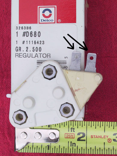
The
voltage regulator in the photo above is used with the
Delco 10SI and 12SI alternators.
Notice that the voltage regulator above has two
flat blade male terminals (see arrows).
There is actually a third terminal of this voltage
regulator, which is the ground at one of the three
mounting screws. One
of the two flat blade terminals is wired to an ignition
switched ON/OFF source, and this circuit can also be used
to operate a dash mounted warning light (The warning light
is an option, not a requirement).
The
other of the two voltage regulator terminals is the
voltage-sensing terminal, and through this terminal the
voltage regulator will monitor electrical system voltage
and make adjustments to the alternator output in effort to
keep system voltage at about 14.2 volts.
When
using the “main junction” power distribution wiring
system, it is very important that the voltage-sensing
terminal of the regulator is wired to the junction.
And when installing the SI series alternators as a
retro-fit up-grade, with a factory type harness using a
main “junction” for power distribution, it is of
great importance to make use of this REMOTE
VOLTAGE-SENSING feature built into the regulator.
In
the next web pages we have photographed a demonstration of
the remote voltage system function and performance.
A lot of photos are used in the next part—and not
much reading. It’s
really quite interesting to see this system work.
To
see the REMOTE VOLTAGE-SENSING feature in action, click
here to continue
|