|
Part 2
BRIGHTER HEADLIGHTS
And
now, a test of performance
after
adding RELAYS for the Head Lights
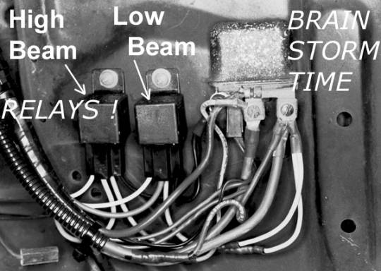
Relays
can be used as "remote control switches."
It takes only a tiny amount of current to turn the
relay ON. But
when switched ON, the relay delivers power directly to the
accessory. ("high
gain" operation)
We
can install headlight relays next to the main power
distribution buss-bar at the horn relay (where the old
voltage regulator was).
The
factory "front lighting system" wire harness is
routed just above that area, in route to the headlights.
We can cut and detour the factory High Beam wire
and Low Beam wire to the relays, and now the factory
system will only have to switch the relays ON, instead of
directly powering-up those big headlights.
The
headlights are up front, and the alternator is the source
of electrical power; and the alternator is mounted at the
front of the engine.
It’s logical and sensible to mount RELAYS up
front. Use
existing wiring to switch the RELAYS ON, and then the
relays will send full power to the lights.
(And use of the relays takes headlight current load
away from the dash wire harness, and so the ignition and
entire electrical system will benefit too.)
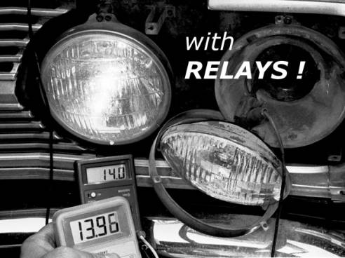
This
test was done after the relay up-grade,
with High Beams ON, engine at idle RPM.
14.0 volts measured at the horn relay buss-bar.
13.96 volts measured at the back of the headlight.
(Before the relays, we had only 11.5 volts at the
headlight, with 14.1 at the Horn Relay, at highway cruise
RPM.)
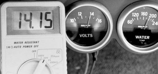
This
test was done after the relay up-grade, with
High Beams ON, engine at highway cruise RPM.
(And it's a good thing our testing is finished,
because the engine is warming up with so much
"running in place.")
With
the current load to support the headlights removed from
the dash wiring and switches, we took away the voltage
drop in the wiring to the dash area.
Now
the dash mounted voltmeter will no longer "lie"
to us when we switch the headlights ON.
The ignition will not become weak.
The dash lights will be brighter.
And other accessories will be more powerful too.
The
first time the car was driven at night, the improvement in
the headlights was remarkable!
Now the lights are very bright.
Everyone
who has used our relay kits for the headlight system
agrees that this is absolutely the best-for-the-money
electrical up-grade.
It adds reliability too, by removing current load
from weak factory connections and switches.
Considering the years of hassle free service,
enjoyment, and safety, this is without a doubt the most
sensible up-grade possible.
It beats out expensive and often over-promoted
luxuries like big sound systems, racing ignition systems,
"high-end batteries," chrome alternators, and
gadgets.
Overall,
the headlight relay up-grade makes these old cars and
trucks more useful and enjoyable to drive.
Two
of our part # RLY-1 Relay Kits are required for the
headlight system up-grade–ONE for LOW BEAMS, and ONE for
HIGH BEAMS. (Even
with "two headlight system" cars.)
And
for people who would like to learn more about electricity,
voltage drop, assembly craftsmanship, Fusible Link wires,
and more, we offer the "tech
is made simple"
book. The
book is easy reading, and it's filled with great photos of
craftsmanship and wiring techniques.
Fundamentals of electricity are explained through
cartoon-like illustrations.
INSIDE OF THE HEADLIGHT SWITCH
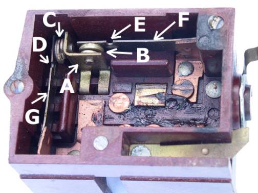
(The
switch shown in the photo was removed from a FORD car.
We ground off the rivet heads, punched out the
rivets, and pried the cover from the switch, for a look
inside.)
Call-out
labels with arrows point to various parts of the two
circuit breakers in a typical headlight switch, shown in
the photo above.
A
= Battery
live "buss-bar," which also serves as mounting
for the stationary contact points of the circuit breaker.
B
& C = Circuit
breaker contact points.
D
& E = Resistance
calibration notches in the movable arm part of the circuit
breaker.
F
& G = Movable
arm, metal strip, part of the circuit breaker.

|